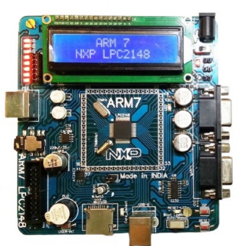
LPC2148 Development Board
$ 90.58
The LPC2148 Development Board LPC2148 ARM7TMDI based microcontroller. The LPC2148 microcontroller has 512KB of internal flash and 32 8K RAM. Following are the salient features of the board. Power supply: DC 9V with power LED On-board linear regulators generate 3.3V/500mA and 5v/500mA from power supply USB connector (as alternate power source) Connectors: Extension headers for all microcontroller pins. RS232 connectors (2) PS/2 connector. JTAG connector. SD/MMC connector. USB B-type connector with Link-LED Other Peripherals: 512Kb I2C based EEPROM Audio power amplifier. 16×2 LCD with back light control. Configurable for manual and automatic program download (ISP) via serial port. 8 controllable LEDs on SPI using 74HC595. User Interrupt, ADC, Buzzer, RTC. 2: System Requirements: Windows XP & Win 7 Serial or Parallel port USB port 3: Starting off & connecting the hardware: After unpacking the LPC2148 board connect a DC supply of 9V/1A to the DC jack to power the board. The LPC2148 board can also be powered through USB. 4: Programming LPC2148 Board: LPC2148 Board can be programmed through serial port UART “0” using “LPC2000 flash utility V2.2.2” is a freeware windows utility used to download the hex file format onto the LPC2148 Board. If your PC does not have a serial port; use a USB to serial converter to download the hex file. Programming LPC2148 Board through ISP. The LPC2148 Board can be programmed through ISP in two modes: 1. Auto Mode 2. Manual Mode Auto Mode: To program in Auto mode you need a full serial cable with DTR & RTS. (Recommended not to use Auto Mode). Manual Mode: To program in Manual mode you need a half serial cable (which just has TX, RX and GND wire connected). And connect the half serial cable to UART0 and power the board. (Recommended mode) Open LPC2000 Flash Utility V2.2.2 Browse File name and Select the hex file to be downloaded. Select Device as LPC2148 Set XTL Freq [KHz] to 12000 Blank Check: Entire Device Select the appropriate com port (See your “device manager” to find out the com port number) Select the Baud Rate in between 9600 and 38400 Uncheck “Use DTR/RTS for Reset and Boot Loader Selection” Click on Read Device ID. To make the board enter programming mode: Hold down ISP and RESET Buttons, then release RESET first and finally ISP. The controller enters the bootloader mode. It will display as “Read device ID Successful”. Click on the Upload to Flash Button. Program uploaded successfully. Click the Rest Button on the Board. That’s it, your hex file is on the board. Package Includes : 1 x LPC2148 Development Board
Related products
-
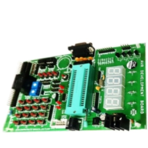 AVR Development BoardSelect options
This product has multiple variants. The options may be chosen on the product page
AVR Development BoardSelect options
This product has multiple variants. The options may be chosen on the product page
-
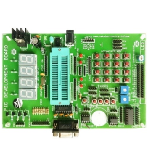 PIC Development BoardAdd to cart
-
LPC2148 Development BoardSelect options
This product has multiple variants. The options may be chosen on the product page